28 November 2009


Upon buying the Sony Blue-ray T10/T11 BD/DVD home theatre system, you will get 2 front speakers, 2 surround speakers, 1 center speaker, 1 subwoofer, 1 AM loop antenna, 1 FM wire antenna, 5 speaker cords (white/ red/ blue/ gray and green), 1 video cord, 1 remote commander, 2 AA R6 batteries, 1 calibration mic, 1 set foot pads, operating instruction manual, speaker and TV connections guide, setup disc (DVD), 1 digital media port adapter (TDM-iP20), and operating instruction manual for the digital media port adapter.
The following file contains detail schematic diagram and instruction for connecting your new Upon buying the Sony Blue-ray T10/T11 BD/DVD home theatre system to speaker and TV set. The connector of the speaker cords and the color tube are color-coded depending on the type of speaker. Connect the speaker cords to match the color of the SPEAKER jacks of the unit. Be sure to match the speaker cords to the appropriate terminals on the speakers: the speaker cord with the color tube to 3, and the speaker cord without the color tube to #. Do not catch the speaker cord insulation (rubber covering) in the speaker terminals.
Get more information on Sony Blue-ray BDV-T10/T11 Speaker and TV Cable Connection Schematic Diagram here – http://www.docs.sony.com/release/BDVT10_connection_EN_ES.pdf – free download PDF file.
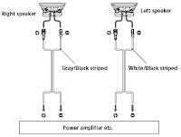
READ MORE -

26 November 2009

Sony XS-4624 Coaxial 2-Way Speaker Subwoofer Wiring Diagram and Cable Connection


The Sony XS-4624 is a Coaxial 2-Way Speaker with 4×6 inch woofer polypropylene cone type, 1 inch tweeter balanced dome type, having 80 Watts maximum input power and 20 Watts rated input power with 4 Ohms impedance, 88 dB/W/m sensitivity and 45 – 25,000 Hz frequency response. The following schematic diagram shows detail wiring diagram and cable connection schematic of Sony XS-4624 Coaxial 2-Way Speaker Subwoofer for Car Audio System.
READ MORE - Sony XS-4624 Coaxial 2-Way Speaker Subwoofer Wiring Diagram and Cable Connection

22 November 2009

Circuit Diagram for 300W Subwoofer Power Amplifier by Rod Elliott

A subwoofer is a woofer, or a complete loudspeaker dedicated to the reproduction of bass audio frequencies, from 150 Hz down as far as 20 Hz, or in rare cases lower. The following link provides detail explanation and description for 300W Subwoofer Power Amplifier circuit and wiring diagram designed by Rod Elliot from Elliott Sound Products.
Find more information about Circuit Diagram for 300W Subwoofer Power Amplifier by Rod Elliott here.
from : wiringdiagrams21.com/
READ MORE - Circuit Diagram for 300W Subwoofer Power Amplifier by Rod Elliott

20 November 2009

Circuit Diagram for Car Subwoofer Driver from RedCircuits


A subwoofer is a woofer, or a complete loudspeaker dedicated to the reproduction of bass audio frequencies, from 150 Hz down as far as 20 Hz.
The following circuit diagrams shows detail electrical schematic for a 22W into 4 Ohm power amplifier, car subwoofer driver. This device is intended to be connected to an existing car stereo amplifier, adding the often required extra "punch" to the music by driving a subwoofer. The power amplifier used is a good and cheap BTL (Bridge Tied Load) 13 pin IC made by Philips (now NXP Semiconductors) requiring a very low parts count and capable of delivering about 22W into a 4 Ohm load at the standard car battery voltage of 14.4V.
This device consists of following parts: Log Potentiometer, Dual gang Linear Potentiometer, 1/4W Resistors, 25V Electrolytic Capacitors, 63V Polyester Capacitors, LED, 100mA NPN Transistors, Dual BIFET Op-Amp, 24 W BTL car radio power amplifier, RCA audio input sockets and 4 Ohm Woofer or two 8 Ohm Woofers wired in parallel.
Find more information about Circuit Diagram for Car Subwoofer Driver here – source: www.RedCircuts.com
READ MORE - Circuit Diagram for Car Subwoofer Driver from RedCircuits

18 November 2009

RANGKAIAN PREAMP MIC PAKAI IC OP-AMP


Microphone Preamp Scheme Using IC Op-Amp
READ MORE - RANGKAIAN PREAMP MIC PAKAI IC OP-AMP

15 November 2009

RANKAIAN PEMANCAR RADIO SW


click picture for ZOOM.
sw radio scheme I have for you a hobby to play with the radio, especially radio frequency SW
READ MORE - RANKAIAN PEMANCAR RADIO SW

12 November 2009

Scheme 88-108 MHz FM transmitter (PLL)


click piturre for ZOOM
READ MORE - Scheme 88-108 MHz FM transmitter (PLL)

08 November 2009

SKEMA VU METER AUDIO TRANSISTOR

READ MORE - SKEMA VU METER AUDIO TRANSISTOR

06 November 2009

Rangkaian elektronika pengatur-penala antena

Di dalam bagian ini di bahas tentang suatu rangkaian-sirkuit pengatur atau penempatan antena untuk pemancar SW gelombang 3-30 Mhz/short wave 3-30 Mhz


Untuk rangkaian transmacth ini sebenarnya tujuannya adalah menempatkan impedansi yang pas antara antena dengan pemancar sehingga terjadi perbandingan 1:1 di bacaan SWRnya,karena dalam penempatan ini rangkaian ini dihubungkan dengan SWR/standing wave ratio. Dengan begitu maksud dari 1:1 adalah satu yang keluar juga satu yang dipancarkan oleh antena bukannya cuma setengahnya saja.Impedansinya umumnya adalah 50 Ohm. Dengan rangkaian ini tenaga maksimum yang bisa lewat rangkaian ini adalah 50 Watt
READ MORE - Rangkaian elektronika pengatur-penala antena

04 November 2009

SKEMA RANGKAIAN SAKELAR SENTUH

READ MORE - SKEMA RANGKAIAN SAKELAR SENTUH

01 November 2009

SKEMA GENERATOR GELOMBANG SINUS


This is iKHz sine beachcomber architect ambit congenital based on agreement of astern Wien arch (see C1-R3 & C2-R4). R5 and R7 acclimated for achievement amplutide setting. Set R5 to apprehend 1V RMS on an Audio Millivoltmeter affiliated to the achievement with R7 rotated absolutely clockwise, or to appearance a sinewave of 2.828V Peak-to-Peak amplitude on the oscilloscope.

Component list:
R1____________5K6 1/4W Resistor
R2____________1K8 1/4W Resistor
R3,R4________15K 1/4W Resistors
R5__________500R 1/2W Trimmer Cermet
R6__________330R 1/4W Resistor
R7__________470R Linear Potentiometer

C1,C2________10nF 63V Polyester Capacitors
C3__________100µF 25V Electrolytic Capacitor
C4__________470nF 63V Polyester Capacitor

Q1,Q2_______BC238 25V 100mA NPN Transistors
LP1___________12V 40mA Filament Lamp Bulb (See Notes)
J1__________Phono chassis Socket
SW1__________SPST Slider Switch
B1_____________9V PP3
Clip for 9V PP3 Battery

Notes:

The bulb must be a low current type (12V 40-50mA or 6V 50mA) in order to obtain good long term stability and low distortion.
Using a bulb differing from specifications may require a change of R6 value to 220 or 150 Ohms to ensure proper circuit's oscillation.
With C1, C2 = 100nF the frequency generated is 100Hz and with C1, C2 = 1nF frequency is 10KHz but R5 requires adjustment.
High gain transistors are preferred for better performance.
READ MORE - SKEMA GENERATOR GELOMBANG SINUS